
As a computer scientist, we deal with several ICs that serve many purposes. Some are microcontrollers. Some are logic gates. Some are just...rather interesting. There's one IC in particular that has its uses as a minimalist oscillator or transmitter with at least 6 components: the 74HC04, the legendary CMOS inverter.
A Logical Start
The 7400-series of chips were first introduced around 1966, so this chip has been around for quite some time. The 74HC04 (introduced around 1983) in particular is a CMOS NOT gate, meaning that when a voltage or high signal is applied to one of the inputs, the resulting output is a low signal or low voltage. 5V will result in 0V, and Hi will result in Lo...you get the idea. As a result, when an oscillating signal is applied in this respect, the result is a square wave. We can filter down square waves back to sine waves with a low-pass filter.
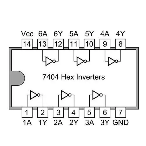
Pin 14 is the Vcc pin (5V MAX), and Pin 7 is the Vss or GND pin. The 74HC04 has 6 inverters, with 6 inputs and 6 outputs. To make an oscillator (and even just the TX itself), you only need to use two or three of the six inverters. I originally got this idea from the VK1SV/VK2COW website, link here: https://people.physics.anu.edu.au/~dxt103/QRP/. It's a great readthrough, and to be honest, the amplifier can be very helpful for other QRP transmitter circuits.
One thing I should add - any generic 74HC04 works best at frequencies from 0 to 20MHz, so I'd be using this on 160m to 17m, or 1.8MHz to 18MHz. Anything above may prove to be unstable and unusable. Some models will operate at much higher frequencies, in the ballpark of >30MHz, others not so much - it all depends upon the propagation delay, or the amount of time in nanoseconds it takes for the high signal to go low and the low signal to go high. Lower tPD times mean higher frequencies of operations, whereas higher times mean lower frequencies. Look for the tPD value in your IC's datasheet.
On the amplifier side of things, the original author decided to use a cheap, commonly-available 2N7000 N-channel MOSFET. It runs at 12VDC and can transform our milliwatt signal into a signal well over a solid watt. Remember, if you are using a different band, you'll need to construct a different LPF for it. Since it's a square wave output, I recommend using a 5- or 7-pole to reduce harmonics drastically.
Basics
Here's an easy and well-established circuit that I found online that, well, basically forms the heart of our transmitter. If you're wanting a true QRP challenge, then this plus a low pass filter is the entire transmitter:

As you can see, we only need a few parts to get this thing up and running! The frequency is dependent upon select values, as seen in the small inset chart. The crystal MUST be in fundamental mode - an overtone crystal will result in an oscillation on its fundamental frequency. R(f) can be any resistor from 1 to 10 megaohms (M). You'll need to use at least 2 of the 6 inverters that the 74HC04 has, but more inverters could mean a cleaner square wave output and even an amplified signal.
Another important note - tie all the inputs that you don't use to ground. Failing to do so can cause instability in the circuit and can lead to stray oscillations or an unclean output, even with a LPF.
Looking Technically
In all reality, this is no more than a basic Pierce oscillator, and we can break it down as such.
R(f) in the above schematic is the feedback resistor. This is important as an oscillator must have feedback in order to function! R(f) is set to a very high value, usually 1 to 10 megaohms. I used 1 megaohm without issue.
Both capacitors (CL1 and 2) are external load capacitances. Crystals are manufactured with capacitances, and these are the capacitances seen at the inverter's input and output. Certain values work with certain frequencies, so ensure that you are taking this into account. To change the crystal's frequency (aka a crude VFO), make CL1 a variable capacitor.
There are many conflicting sources online as to whether it's necessary or not, but R(s) appears to be a drive current-limiting resistor and, in my opinion, is necessary. This ensures that the crystal is not overdriven. An overdriven crystal can stress the component to the point of failure or fracture, making the crystal unusable. While it can push out significantly more power, there must be a balance between power and efficiency if you'd like to keep the crystal running for quite a while. So again, a higher value will give the crystal a longer lifespan while a low value will help the oscillator start faster. 1kiloohm, the value I used, seems to balance the best of both worlds, but a slightly lower value my be better. Try 470 or 220 ohms.
Now let's look at the main IC of the circuit, the 74HC04. The first inverter stage acts as a buffer, converting the crystal's sine wave into a very dirty square wave. The second and optionally additional inverter stages act as filters and amplifiers, filtering the impure wave into a close-to-perfect square wave. A 74HC04 will oscillate on its own in a free-running oscillation, however adding Y1, or the crystal allows the 74HC04 to oscillate on a certain frequency specified. In a nutshell, the crystal acts as a frequency filter! Y1 can also be replaced with a ceramic resonator, which will allow for a greater frequency pull when used with a variable capacitor, generally a range over several KHz.
In addition, there are also many stray capacitances that will affect the crystal's frequency. This can include things like breadboard strips, solder joints, PCB parasitic capacitances, etc. So, while a 3.579MHz crystal may be on 3.579, in reality, it could be setting around 3.580, 3.576, and so on - in essence it won't be spot on 3.579MHz. And it might not even oscillate at all.*
Since we can't use square waves on the air due to squares having MANY odd harmonics, we need to install a well-built low pass filter that will attenuate these harmonics. Ensure that your harmonics are well attenuated by using at least a 5-pole Chebyshev. You can use axial inductors and standard ceramic capacitors since this is a QRP circuit. For future reference: for higher power circuits you'll need to wind your own inductors and use NP0 caps.
* A Word about Component Values and Construction
Well to end this post, I did assemble this oscillator and to my surprise it worked! It did NOT work the first time or the second. I did end up snapping, popping and cracking a 7404 chip due to excessive voltage as well. In the end, here's what I found. It's going in my memorabilia of successful failures, and plus the crack on the chip kinda looks cool.
Components aren't very finnicky depending upon the frequency of the crystal. I found in building mine that 22pF capacitors and a 1K drive resistor did just fine when I assembled my 80 meter version. I replaced the crystal with a 7.023MHz crystal and it still oscillated! You must pay attention to how you wire everything up on a breadboard as well. Cheap, mass-produced breadboards, I have found, are generally not the best to prototype with but are fine for temporary setup. You might end up with issues such as loose pin connections, shorted rows, and much more. Be aware of this, as it may hinder your build and cause your circuit to not oscillate at all. Use a breadboard, get it to oscillate, and then permanently build it on a piece of perfboard, or if you know what you're doing, build it directly onto perfboard.
So in the end - EXPERIMENT!!! Don't be afraid to try different values or add in components. As always, to use this on air, a LPF is a must - don't skimp out on it! Testing without a LPF transmitted relatively strong harmonics well up to the 8th multiple, around 28.6MHz, on my shortwave receiver!
I have found no issues getting this oscillator to start whether you key the voltage line or key the ground line. There's little to no chirp, and the tone never wavers around or dips like some DIY oscillators and transmitters. Besides being a QRP transmitter, this can also work as a QRSS beacon. Just add an Arduino auto-keyer alongside an optocoupler or relay on the key line.
That's all I got for now, but stay tuned for much much more, including a GRAND TOUR of the final ham shack assembly!
No comments:
Post a Comment