Do you have a radio that you want to run digital modes on? That's great, but you know that you don't want to spend hundreds of dollars on a sophisticated interface. Let's face it - a soundcard interface is made up of audio transformers and a way to key your rig, so why pay more for something so simple?
I want to talk about the most simplistic interface board ever created. It's so simple that one could even homebrew their own! It's the Easy-Digi interface, available on eBay. This neat little gadget is sold by KF5INZ on eBay for a VERY reasonable price. The board is easy to follow and can be wired up to your satisfaction and need.
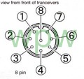
Above is my Easy-Digi board with an FTDI232 board acting as a serial controller. On the input side I have wired up an 8-pin microphone connector. Because I am going to use this on the TS-660 in the near future, I have configured it for that radio. The pinout is as follows for the TS-660 and many other Kenwood radios of the era:
I have only one problem with this board: Whenever I power everything up and plug the interface into my radio, the radio always remains keyed. I hopped on QRZ.com forums and began to search for answers. One operator suggested I test voltage levels at the DTR and RTS lines. So I took out my voltmeter and began to diagnose. To my surprise, the DTR and RTS lines were 5V when my computer software wasn't keying, and 0V when it was keying. As I began to brainstorm ideas on how to fix this, a thought hit me - what if I used an inverter like the 74LS04 series?
A 74LS04, or any other inverter, works as a NOT logic gate. When a high signal is placed on the input of an inverter, the resulting output is low. When the input is low, the output is high. Likewise, if my theory is correct, 5V of input will be 0V of output, and 0V of input will be 5V of output.
I had somewhat of a "eureka!" moment when I thought of this. I'm going to try it out later and see how it works. Nominally, a 74LS04 needs 5V of supply power, which the FTDI chip already supplies.
To summarize - if you need a soundcard interface that is dirt cheap and easy to diagnose and troubleshoot, the Easy-Digi is, without a doubt, the best choice for the money and functionality.
Link to buy the Easy-Digi is here. The Easy-Digi is proudly made in the USA.
Instead of using a 74LS04 with 6 inverters, you could use the classic transistor inverter circuit shown below.
UPDATE (2/6/2023): In doing some more digging online, I've concluded that the chip is fake. If you have a chip model number 0x6001 (found using FT_Prog, available online), chances are it is fake. The ROM can't be reprogrammed to invert the signals. If this is the case, just build an inverter circuit.


No comments:
Post a Comment