
If you're like me, you like to build things and experiment with them - you constantly ask yourself, "how does this work?" QRP operation has brought me to that question many times, and today, I want to discuss a few QRP designs I happened to stumble upon. I'm sure you've also seen these circuits across the web. Today, I'd like to showcase some simple transceivers that you can build in a very short amount of time for almost nothing!
The Pititico
The Pititico is the brainchild of Miguel, PY2OHH. It utilizes a single transistor as a mixer, an oscillator, and an amplifier. A simple 2N3904 can be used or any other NPN (BC547, 2N2222, etc.) as long as the circuit still oscillates cleanly. Below is the small, simple schematic diagram with finalized corrections made to the final product:

It's a simple circuit, and in conjunction with an appropriate low-pass filter, this would be the perfect pocket transceiver to carry with you anywhere! Miguel used a telephone speaker (~300 ohms) as the audio output, but I don't see why a crystal earpiece (>2K ohms) wouldn't work. Better yet, an LM386 would pair nicely with this but it might take away from the simplicity.
The components in C1, L1, and R2 provide the frequency offset.
To prevent "TX pop" each time the key is depressed, Miguel added 2 1N4148 diodes to the output between the audio out and ground lines.

This is the earlier schematic. If you'd like to build this, build it according to the first schematic but add the two diodes as shown in schematic #2. According to Miguel, he has made at least 3 clear and concise contacts (at the time of writing his article) with the Pititico. That's not bad, considering that he is using milliwatts of power. I've heard of some hams getting the power output to a solid 1W.
Ciprian, YO6DXE (aka DXExplorer on YouTube) made his own version of the Pititico built into what looks like a mini paraset box. His files, PCB designs, and schematics are available on the DXExplorer website. In addition, David, DL1DN, modified the Pititico to operate on 10 meters. The best part is that he made it across the pond to the states according to the Reverse Beacon Network. Check out his schematic below. The cool thing is that he was only running it off of a 9V cell, which I can ony imagine was giving him just a few hundred milliwatts of power! On 10 meters, especially during this cycle, that's a true testament and feat to CW operations!

Only three components need changed, X1, C1, and C2 (both capacitors are part of the oscillator circuit!).
The One Transistor Marvel
This next circuit comes from the genius mind of the legendary Dave Ingram, K4TWJ (SK). It, like the Pititico, uses only one NPN transistor, albeit with a heavy power reduction. In essence, it was originally supposed to be a transmitter, but with the addition of a crystal earpiece and a 10uH inductor, one can make it a full blown QRPp transceiver. Power is claimed to be between 70mW and 200mW depending on how the circuit is built. Dave published many of his works in a book titled "International QRP Collection," and this book can still be purchased today. I'd highly recommend it as there are many QRP designs and techniques for designing your own QRP transmitter or transceiver.
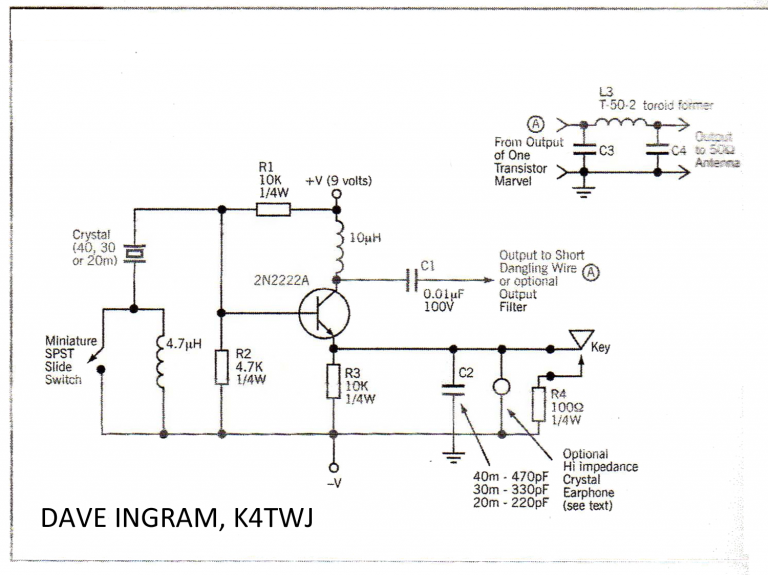
The complete PDF article can be found here at archive.org for those wanting to reference the text. In the design, the 4.7uH inductor provides some form of offset so you can copy a station and complete a QSO. This was designed as more of a novelty for hams who stay at hotels or attend hamfests and hamventions, where short-range communication is a common activity. However, there are some of us hams who like a challenge and if connected to a resonant dipole, this has the potential to make a successful QSO tens of hundreds of miles away. Dave described this circuit as four things: a QRP transmitter, a wireless BFO/receive converter, a personal emergency beacon, and/or a low-gain HF micro transceiver. Whatever you want to call it, I call it a tiny and mostly inexpensive way to get on the air!
The XBM Specials
Roger from the UK, G3XBM, has designed many QRP CW circuits and posts them to his blog page. I have taken note of the circuits such as the XBM80-2 and the XBM10-2 (10 meter edition of the 80-2):


These are simple 2-transistor designs, with one transistor acting as the mixer/oscillator and the other as a crude audio amplifier. Don't be fooled by low power output - real QRP requires quiet and uncrowded spaces to work properly. According to Roger, these circuits are good for hearing -100dBm signals. To put that into perspective, that is 100dB below the average noise floor! Of course, one could simply add an LM386 amplifier instead of Hi-Z crystal earphones, but that's taking away from the beautiful simplicity. I should also add that many hams have taken the liberty of moving these circuits to different frequency bands such as 40m. They claim to work just as well.
Roger has also built the UU80B, also known as the XBM80-1.

If you take a closer look, you'll find that it's almost the exact same circuit as the Curumim, another micro transceiver built by PY2OHH. The only addition is a small NPN audio amplifier. C1 provides RX audio offset when the key is closed/open. It is about 600Hz.
Conclusions
Building QRP radios has taught me a lot about how radios work and how each component plays a crucial role in completing a QSO. It amazes me that with only one or two transistors, you can make a fully functional radio that has the potential to get across the state, country, or even the ocean. While some hams view QRO as the way to go, QRP building is an excellent starting point for any new amateur. Building such circuits as shown above will not only be satisfying when they work the first time, they will teach you a lot about the hobby. 20 years down the road, you may just pull this out of one of your desk drawers and make a QSO to a distant nation with ease!
Building QRP circuits is an art, and it is one that has to be considered with precision. When building these circuits, use qualitative parts rather than quantitative. While 5-10% resistors or better yet 20% are cheap, try sticking with 1-2% tolerances. The tighter the tolerance, the better chance you have of successfully making a fully-functional circuit without any hiccups or instability. Opt for transistors made by reputable companies such as Texas Instruments, Toshiba, Central Semiconductor, etc. These will ensure that you get more power output than a generic bargain pack of transistors, which may only provide you with a max of 100mW or less. Cheap transistors may also degrade signal quality, making QSO attempts almost pointless and fruitless. Metal-cased transistors are also better for QRP circuits as they can dissipate heat better than their plastic-cased counterparts. Add too much power and you end up releasing the magic smoke demons. Also, as a piece of advice, add in a way to swap out crystals to change frequencies, whether that be via a variable capacitor or a switch.
The best thing is that many of these circuits can be made for pennies on a dime. There's not much to them, giving you free reign of any modifications you may want to try. Perhaps you'd like to make a passive RC or LC audio bandpass filter for around 800Hz or so to filter out any QRM. Maybe you'd like to move the circuit to a different frequency band. Whatever the case may be, QRP is all about experimentation. Experiment with different transistors, capacitor values, etc.
Fabricating PCBs for QRP circuits is easy, especially if you love connect-the-dots games. I use copper chloride etchant which has worked great for me - just don't breathe the stuff in as it's highly toxic! I have a fabrication post regarding how to make the solution.
If you're still stuck, I recommend checking out Peter Parker, VK3YE's channel. He goes into detail about QRP circuits and covers basic principles and troubleshooting steps. QRP circuits, if troublesome, can be hard to troubleshoot, but just think about full size rigs!
I wrote a blog post early on in this website's infancy about how to operate QRP. I have found that QRP relies on many things, including the radio used, the antenna, the space/place, the time of day, and the frequency. Remember to take all of these into account. Using a QRP rig on a short piece of wire will not be as effective as using a resonant dipole. Again, power output means almost nothing unless you're going up against 100 watt transmitters. If you're on a clear frequency, chances are you'll be heard. For reference, you can also use the Reverse Beacon Network to see how far your signal gets out. For CW, a report of single digit decibel levels isn't necessarily bad - CW is optimized for weak SNR.
So what are you waiting for??? Grab that soldering iron and get to building!!!
No comments:
Post a Comment